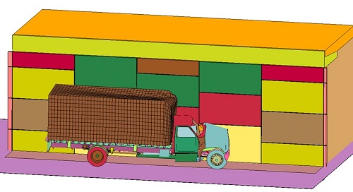
Analysis and Design of the Roadside Safety Features for Safety Performance
Texas Transportation Institute (TTI) researchers are investigating the performance of a crash wall design to determine its effectiveness in reducing the damage to mechanically supported earth (MSE) wall panels during a vehicular impact. The simulations are based on Test Level 4 impact conditions of the new AASHTO Manual for Assessing Safety Hardware (MASH). This involves a 10,000-kg single unit truck (SUT) impacting at 90 km/h (56 mi/h) and 15 degrees. Three MSE wall finite element models have been developed: (1) a typical section of a MSE wall excluding the crash wall to observe damage of the wall panels when impacted directly, (2) a MSE wall with a crash wall to quantify reduction in damage of the panels, and (3) a MSE wall with a crash wall and anchors to provide positive interaction between the wall panels and the crash wall.
Simulations were conducted on the TRACC cluster using the LS-DYNA®/MPP nonlinear finite element code as the core solver. The model included explicit definitions of many details of the MSE wall system (including soil mass, steel reinforcement strips, and concrete wall panels). The vehicle used in the simulations was a single unit truck model developed by the National Crash Analysis Center and Battelle. TTI researchers modified the existing SUT model to represent the MASH 10000S box truck.
In the figures below, the upper left figure shows SUT impact on the MSE wall panels and the upper right figure for SUT impact on the crash wall. Damage to the MSE wall panels (lower figure) resulting from direct vehicle impact was extensive and would require very costly repairs. Damage was significantly reduced by the inclusion of the crash wall. Based on these simulations, a 0.2 m (8 in.) thick crash wall is considered adequate to reduce damage to the MSE wall below levels that would require repair.
Impact on panels (left) and Impact on crash wall (right)
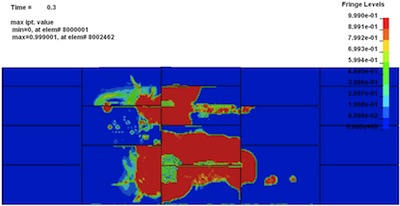
Panels damage due to direct impact on MSE wall panels
Simulation of Oat Ditch Bridge Pier Failure
Simulations were performed to analyze the failure of the Oat Ditch Bridge on I-15 in California (Bridge ID: 54-0270R). The bridge is a 5-span continuous reinforced concrete slab supported on 4 reinforced concrete columns in each of the pier bents. Each column was supported by an individual rectangular footing. Although analyzed for scour in 2000 and found to be not scour critical, three columns at bent five of the bridge failed during the flood on 08/19-20/2003. As proposed by the California DOT, during the flood the bending moment created by hydraulic forces caused the concrete failure at the juncture of the columns and the cap-beam in the pier bent. Numerical simulations using LS-DYNA®/MPP on the cluster produced the observed failure mode.
Deformation of the soil around the pier footing
For further information contact: This email address is being protected from spambots. You need JavaScript enabled to view it.